
ADSS Cable Hardware Selection: A Technical Guide to Fiber Optic Fittings
Date: 2026-07-06
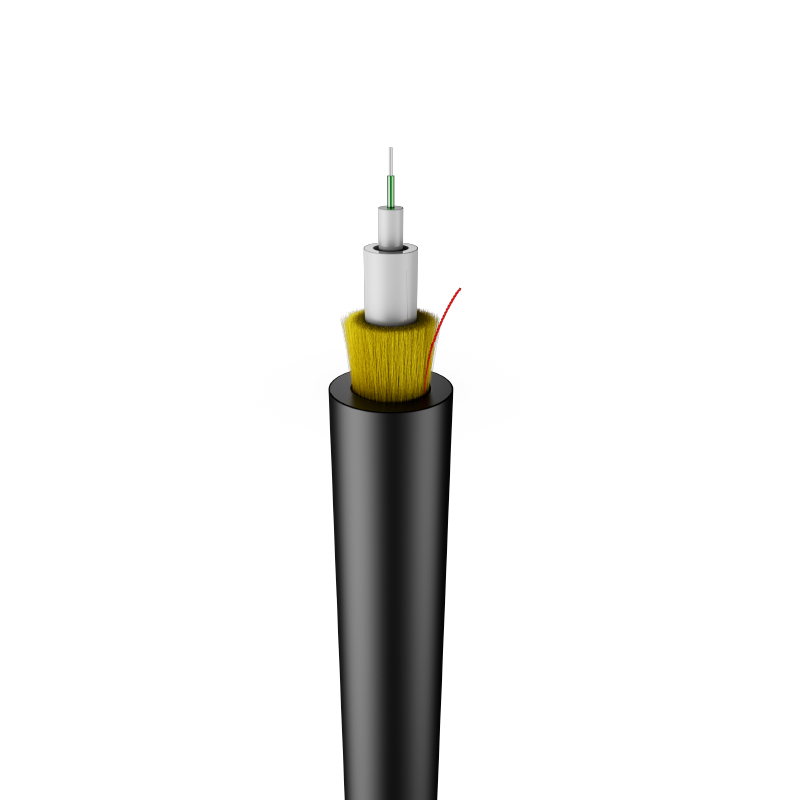
All-Dielectric Self-Supporting (ADSS) cables have become the preferred solution for aerial fiber deployment in medium-voltage and high-voltage power line corridors. Unlike traditional messenger-wire aerial cables, ADSS carries its own tensile load through aramid yarn strength members integrated within the cable jacket. This design eliminates metallic components, making it safe for installation on energized power lines. However, the absence of a steel messenger wire shifts the mechanical burden entirely to the cable hardware—the fittings that attach, tension, and support the cable at poles and towers.
This guide examines the critical hardware components for ADSS deployment, the engineering principles behind their selection, and the field practices that ensure long-term reliability in one of the most mechanically demanding environments in fiber infrastructure.
The Mechanical Environment: Understanding ADSS Loading
ADSS cables experience a complex loading profile that differs significantly from lashed or messenger-supported aerial cables:
Primary Load Sources
- Tensile load: The cable's own weight between supports creates a catenary tension. Span length, cable weight, and sag tolerance determine the base tension.
- Wind load: Lateral wind pressure on the cylindrical cable creates oscillating forces. The cable diameter and the installation region's wind zone classification determine design loads.
- Ice load: In cold climates, radial ice accumulation increases both weight and wind exposure. Ice loading is typically specified as a radial thickness (e.g., 12.5mm) with corresponding density.
- Aeolian vibration: Wind passing over the cable creates vortex shedding, inducing high-frequency, low-amplitude oscillations. Without damping, these vibrations cause fatigue at support points.
- Galloping: Large-amplitude, low-frequency oscillations caused by asymmetric ice buildup or wind angles. Galloping can generate forces exceeding static design loads by 200%.
The hardware at each support point must manage these loads without damaging the cable's dielectric structure. The aramid strength members carry tensile loads; the hardware must distribute those loads evenly and protect the cable jacket from abrasion, crushing, or UV degradation.
Hardware Component Categories
Tension Clamps (Dead-End Assemblies)
Tension clamps anchor the cable at termination points and angle poles where the cable route changes direction. The clamp grips the cable without crushing the optical fibers or damaging the jacket.
Design types:
| Type | Mechanism | Application |
| Wedge type | Tapered jaws grip tighter as tension increases | Standard spans, low to medium tension |
| Helical preformed | Armor rods wrap around the cable, distributing the load over a length | High tension, large diameter cables, critical spans |
| Compression type | Hydraulic compression forms a permanent bond | Permanent terminations, highest reliability |

Critical selection criteria:
- Cable diameter range: The clamp must match the actual cable OD, including jacket tolerances. Oversized clamps slip; undersized clamps crush.
- Load rating: The clamp's rated breaking strength (RBS) should exceed the maximum anticipated tension by a safety factor of 2.5 to 3.0.
- Armor rod length: For helical preformed clamps, the armor rod length determines load distribution. Standard lengths are 600mm, 900mm, and 1200mm. Longer rods reduce stress concentration but require more installation space.
- Material: Aluminum alloy body with stainless steel hardware is standard. Hot-dip galvanized steel is acceptable for non-corrosive environments but adds weight.
Suspension Clamps
Suspension clamps support the cable at intermediate poles where the route continues straight. Unlike tension clamps, suspension clamps allow longitudinal movement to accommodate thermal expansion and contraction.
Design types:
| Type | Characteristics | Best For |
| Single layer | Simple bracket with elastomer insert | Short spans, low wind zones |
| Double layer | Two elastomer-lined clamps with a spacing bracket | Long spans, high wind loads, vibration-prone areas |
| Armor rod suspension | Preformed rods with suspension bracket | Large diameter cables, maximum protection |

Selection criteria:
- Vertical load rating: Must support the cable weight across the maximum span with ice loading.
- Dynamic load capacity: Should accommodate wind-induced oscillation without fatigue failure.
- Cradle radius: The clamp's curvature must match the cable's minimum bend radius to prevent kinking or microbending losses.
- Elastomer hardness: Shore A 60–70 is typical. Too soft allows excessive movement; too hard transmits vibration to the cable.
Downlead Clamps
Downlead clamps secure the cable as it transitions from the aerial span to the pole or tower, guiding it to the splice closure or termination box.
Key considerations:
- Spacing: Typically installed every 1.0–1.5 meters along the downlead. Closer spacing reduces wind-induced cable movement near the pole.
- Clamp type: Stainless steel strap clamps with polymer lining prevent jacket abrasion. Rigid clamps are preferred over flexible ties for long-term stability.
- Exit angle: The cable should exit the suspension clamp at a controlled angle (typically 15–30 degrees from vertical) to minimize bending stress at the transition point.

Vibration Dampers
Vibration dampers dissipate aeolian vibration energy before it reaches the support hardware. Without dampers, the cyclic bending at clamp points can cause aramid yarn fatigue and jacket cracking within 2–3 years.
Common types:
| Type | Principle | Application |
| Stockbridge | Two weights on a flexible steel rod, tuned to cable frequency | Standard spans, proven design |
| Spiral vibration damper | PVC or metal spiral wrapped around cable | Short spans, distribution cables |
| Flexible spacer-damper | Combines damping with phase separation | Multi-circuit power lines |
Placement: Stockbridge dampers are installed at calculated distances from the support point, typically 0.5–1.5 meters, based on cable diameter and tension. Incorrect placement reduces effectiveness by 50% or more.
Armor Rods
Armor rods are helical aluminum rods that wrap around the cable at support points, reinforcing the cable against bending, abrasion, and compressive loads from clamps.
Functions:
- Distribute clamp pressure over a longer cable length
- Protect the jacket from direct contact with metal hardware
- Provide additional stiffness at the support point to reduce dynamic stress
- Extend the fatigue life of the cable by 3–5x in vibration-prone environments
Selection: Rod inner diameter must match cable OD within ±1mm. Rod length is selected based on tension and vibration risk: 600mm for standard applications, 900mm for high wind zones, 1200mm for critical spans or large diameter cables.
Material Selection and Corrosion Resistance
ADSS hardware operates in environments that range from coastal salt air to industrial pollution to high-altitude UV exposure. Material selection must account for these conditions:
| Component | Standard Material | Corrosive Environment Upgrade |
| Clamp body | Aluminum alloy 6061-T6 | Marine-grade aluminum or stainless steel 316 |
| Hardware (bolts, nuts) | Stainless steel 304 | Stainless steel 316 or duplex 2205 |
| Armor rods | Aluminum alloy | Aluminum alloy with anodized coating |
| Elastomer inserts | EPDM | Silicone for extreme temperatures or UV exposure |
| Suspension brackets | Hot-dip galvanized steel | Stainless steel 316 or aluminum alloy |
In coastal or chemically aggressive environments, the incremental cost of 316 stainless steel hardware (typically 15–25% premium) is recovered many times over by avoiding corrosion-related failures and replacement truck rolls.

Installation Best Practices
Pre-Installation Verification
- Verify cable diameter matches hardware specifications. Manufacturing tolerances in cable OD can cause clamp slippage or over-compression.
- Inspect armor rods for straightness. Bent rods create uneven load distribution.
- Confirm pole strength. ADSS hardware adds eccentric loads that must be included in pole structural calculations.
Tensioning Procedure
- Use a dynamometer or tension meter to verify sag-tension calculations in the field. Design tension and actual tension often diverge due to temperature, wind, and span length variations.
- Apply tension gradually. Rapid tensioning can shock-load the cable and hardware.
- Maintain minimum bend radius (typically 20x cable OD) during installation. Temporary bending during stringing is acceptable; permanent bending at support points is not.
Clearance Requirements
ADSS cables installed on power line structures must maintain electrical clearances per IEEE 524 or local utility standards:
- Horizontal clearance: Typically 1.5–2.0 meters from energized conductors, depending on voltage class.
- Vertical clearance: ADSS is typically installed below the lowest power conductor to minimize electrical field exposure.
- Tracking resistance: The ADSS jacket material must have adequate tracking resistance (IEC 60587, Class 1a or better) for the voltage level of adjacent conductors.
Testing and Quality Assurance
Hardware reliability is validated through mechanical testing that simulates decades of field loading:
- Tensile testing: To 50% of the rated breaking strength for 1 minute, then to 75% for 10 seconds. No slippage or permanent deformation.
- Vibration fatigue:10 million cycles at 25Hz with amplitude ±0.5mm. No cracking, loosening, or cable damage.
- Thermal cycling:-40°C to +70°C, 20 cycles. Hardware and elastomer components must retain function.
- Corrosion testing:1000-hour salt spray per ASTM B117 for coastal applications. No red rust on critical surfaces.
At Carefiber, ADSS hardware is sourced and tested to meet or exceed these protocols. Test certificates are available for project documentation and utility compliance requirements.
Specification Checklist for ADSS Hardware Procurement
- Cable diameter range and tolerance compatibility
- Rated breaking strength with safety factor verification
- Clamp type matched to application (tension, suspension, downlead)
- Armor rod length and diameter specification
- Vibration damper type and placement calculation
- Material grade for environmental conditions (standard, marine, industrial)
- Elastomer hardness and UV resistance rating
- Corrosion test certification (salt spray for coastal/industrial)
- Mechanical test reports (tensile, vibration, thermal cycling)
- Installation accessories included (wrenches, torque specs, spare hardware)
Conclusion
ADSS cable hardware is not an accessory. It is a structural system that determines whether an aerial fiber deployment lasts 25 years or requires replacement in 5. The selection of tension clamps, suspension assemblies, vibration dampers, and armor rods must be based on engineering analysis of the specific loading environment, not catalog convenience or unit cost.
By specifying hardware with appropriate load ratings, material grades for the deployment environment, and validated test documentation, network operators can ensure that the mechanical infrastructure supporting their optical network is as reliable as the fiber itself.
For project-specific ADSS hardware recommendations, load calculations, or test documentation, contact Carefiber's technical support team.
Sive product breadth, the company maintains its role as a key contributor to the global digital infrastructure.
For more information on specialized optical solutions and manufacturing capabilities, please visit: https://www.carefibergroup.com/