
Fiber Optic Splice Closure Selection: A Technical Guide for Long-Term Network Reliability
Date: 2026-05-09
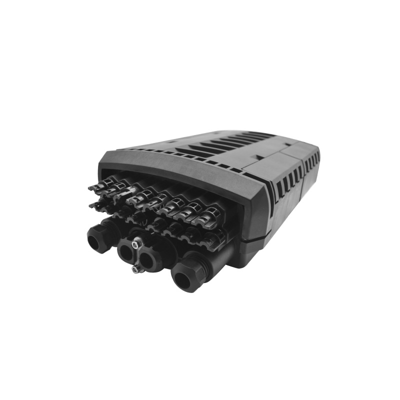
When designing a fiber optic network, engineers often focus on cable specifications, splitter ratios, and connector types. Yet the splice closure—the protective housing that joins, splits, and manages fiber segments—frequently receives less scrutiny than it deserves. In practice, a poorly specified closure is one of the most common sources of field failures, service interruptions, and costly maintenance visits. This guide examines the critical selection criteria for fiber optic splice closures, with a focus on the technical attributes that determine real-world performance over a 10-to-15-year deployment lifecycle.
Understanding the Role of the Splice Closure in Network Architecture
A splice closure serves three primary functions in an optical distribution network (ODN):
- Physical Protection: It shields fusion splices, mechanical splices, and splitter modules from moisture, dust, UV radiation, and mechanical stress.
- Fiber Management: It provides organized routing, strain relief, and bend-radius control for incoming and outgoing cables.
- Environmental Sealing: It maintains a stable internal environment regardless of external temperature fluctuations, water pressure, or chemical exposure.
In aerial, buried, and duct installations, the closure must perform these functions without degradation for the entire service life of the network. A failure at this node typically affects multiple subscribers and requires a truck roll to a location that may be underground, on a pole, or in a handhole.
IP Ratings: Beyond the Marketing Label
The Ingress Protection (IP) rating is the most visible specification on any closure datasheet, but the number itself tells only part of the story.
IP68: What It Actually Means
An IP68 rating indicates complete dust protection (6) and sustained water immersion resistance (8). However, the "8" in IP68 is not a fixed standard—it is manufacturer-defined. One supplier's IP68 may be tested at 1 meter for 24 hours, while another tests at 3 meters for 72 hours. For buried or flooded duct applications, the depth and duration of the test matter significantly.
At Carefiber, splice closures undergo a 72-hour immersion test at 2-meter depth, followed by cyclic temperature stress from -40°C to +65°C. This protocol exceeds the minimum requirements for IP68 and aligns with the actual stress profile of outdoor infrastructure in variable climates.
The Real Weak Points: Gaskets and Entry Ports
The IP rating applies to the enclosure as a whole, but water ingress typically occurs at specific failure points:
- Gasket compression set: Over time, elastomeric gaskets lose resilience, particularly when exposed to UV and ozone in aerial installations. Silicone and EPDM compounds perform better than basic rubber formulations.
- Cable entry ports: Round cable grommets must accommodate a range of cable diameters without deformation. Split-seal designs allow retrofit entry but introduce additional sealing surfaces.
- Housing joints: Clamshell or dome closures rely on compression seals at the mating flange. Torque specifications must be maintained during installation, and re-entry requires careful inspection of gasket condition.
Capacity Planning: Today vs. Tomorrow
Splice closure capacity is specified by the number of fibers and cables it can accommodate. However, effective capacity depends on the internal configuration:
| Configuration | Typical Fiber Count | Use Case |
| Inline, single cable | 12–48 fibers | Drop cable extension, repair splice |
| Inline, multi-cable | 48–144 fibers | Distribution point, mid-span access |
| Branching (T or Y) | 96–288 fibers | Splitter integration, feeder-to-distribution transition |
| High-density dome | 288–576 fibers | Centralized splitting, large count fiber management |
A common specification error is sizing the closure for the initial fiber count without accounting for future growth. In FTTH networks, splitter upgrades, fiber additions, and route changes are routine over a 10-year period. A closure that is at 90% capacity on day one forces a mid-life replacement, doubling the installation labor and introducing a new potential failure point.
Best practice: Specify closure capacity at 50–60% of maximum for the initial deployment, with modular tray or cassette systems that allow reconfiguration without replacing the housing.
Installation Environment: Aerial, Buried, and Duct
The installation method dictates the mechanical requirements for the closure:
Aerial Installments
- Wind loading: The closure and its contents add mass to the cable span. Pole-mounted closures require lashing wire or bracket mounting that can withstand wind-induced vibration.
- Temperature cycling: Aerial closures experience the most extreme temperature swings. Material selection must account for thermal expansion mismatch between the housing, gaskets, and cable jackets.
- UV exposure: Polycarbonate and ABS housings degrade under prolonged UV exposure. UV-stabilized formulations or opaque colorants extend service life.
Buried Installments
- Soil chemistry: Acidic soils, salt exposure in coastal regions, and industrial contamination can degrade polymer housings. Chemical resistance testing (ASTM D543) should be referenced for the specific deployment region.
- Ground loading: Buried closures in traffic areas must withstand incidental loading. Mechanical impact resistance (IK rating) is relevant here.
- Water table: In high water table regions, sustained hydrostatic pressure tests beyond standard IP68 are warranted.
Duct Installments
- Space constraints: Duct closures must fit within standard duct diameters and allow pulling without snagging.
- Flooding: Underground ducts often flood seasonally. The closure must maintain seal integrity under repeated wet-dry cycles.
Splice Protection: Mechanical vs. Heat-Shrink
Within the closure, individual fiber splices require protection against bending and tensile stress. Two methods dominate:
Heat-Shrink Splice Protectors
- Construction: A metal strength member, hot-melt adhesive, and polyolefin shrink tube.
- Advantages: Superior long-term reliability, excellent moisture barrier, standardized dimensions compatible with most tray systems.
- Disadvantages: Requires a heat gun or oven for installation, adds field time, and cannot be removed without cutting.
Mechanical Splice Protectors
- Construction: A plastic clam-shell or crimp-style housing with internal gel or adhesive.
- Advantages: No heat required, faster installation, reusable in some designs.
- Disadvantages: Higher insertion loss variability, potential for long-term creep or gel migration, generally not recommended for buried or submerged applications.
For outdoor closures intended for 10+ year service, heat-shrink protectors remain the industry standard. Mechanical protectors are acceptable for temporary repairs, indoor applications, or aerial drops where re-entry is anticipated.
Internal Organization: Trays, Cassettes, and Splitter Integration
The internal layout of the closure determines how easily technicians can perform re-entry operations without disturbing existing splices.
Splice Trays
- Stacked trays:Common in dome closures, allow high fiber count in a compact volume. Each tray typically holds 12–24 splices.
- Hinged or removable trays: Facilitate access to lower trays without disassembling the entire stack.
- Fiber routing: Trays should include radius-limiting features (minimum 30mm bend radius for G.657 fiber) and strain relief anchors for both cable and individual fibers.
Splitter Integration
Micro PLC splitters (1x2, 1x4, 1x8, 1x16) can be mounted within the closure, converting a distribution point into a passive splitting node. This integration:
- Reduces the number of external enclosures
- Simplifies the ODN topology
- Requires careful thermal management, as splitters generate minor heat and have specified operating temperature ranges
When integrating splitters, verify that the closure's internal volume and tray spacing accommodate the splitter dimensions without pinching fibers or violating bend radius.
Material Selection: Housing, Hardware, and Gaskets
| Component | Common Materials | Considerations |
| Housing | PP (polypropylene), PC (polycarbonate), ABS | UV stability, impact resistance, chemical resistance |
| Hardware | Stainless steel 304/316 | Corrosion resistance in coastal or chemically aggressive environments |
| Gaskets | Silicone, EPDM, NBR | Compression set resistance, temperature range, chemical compatibility |
| Internal tray | ABS, PC | Dimensional stability, fiber-friendly surface finish |
For marine, coastal, or industrial environments, 316 stainless steel hardware and EPDM gaskets are recommended over standard configurations. The incremental material cost is negligible compared to the cost of a field failure and replacement.
Testing and Quality Assurance
A splice closure is only as reliable as the testing it undergoes before deployment. Key validation protocols include:
- IP verification: Sustained immersion with periodic inspection for water ingress
- Thermal cycling:-40°C to +65°C with humidity, repeated for 10+ cycles
- Mechanical impact: IK08 or IK09 per IEC 62262 for buried applications
- Tensile loading: Verification that cable retention and strain relief systems hold under specified pull forces
- Re-entry simulation: Multiple open-close cycles to verify gasket resilience and seal recovery
At Carefiber, every production batch undergoes sampling-based testing for IP68, thermal cycling, and mechanical impact. Test reports are retained for traceability and provided to customers upon request for project documentation.
Specification Checklist for Procurement
When evaluating splice closure suppliers, use the following checklist to ensure technical alignment with project requirements:
- IP rating with defined test depth and duration
- Cable entry port range and type (round, oval, split-seal)
- Maximum fiber and cable count with 50% growth margin
- Splice tray capacity and compatibility with heat-shrink protectors
- Splitter integration capability (if applicable)
- Material specifications for housing, hardware, and gaskets
- Operating temperature range aligned with deployment climate
- Re-entry design (tool-less preferred for field efficiency)
- Quality test documentation and batch traceability
- Installation accessories included (mounting brackets, lashing wire, spare gaskets)
Conclusion
The splice closure is not a commodity component. It is a long-term protective system that must maintain seal integrity, fiber organization, and mechanical stability across a range of environmental stressors for the full service life of the network. Procurement decisions based solely on unit cost or basic IP ratings introduce avoidable risks that manifest as service outages, maintenance costs, and premature infrastructure replacement.
By evaluating closures against the technical criteria outlined in this guide—sealing performance validated by rigorous testing, capacity with growth margin, material suitability for the installation environment, and internal organization that supports both initial installation and future re-entry—network operators can specify products that deliver the reliability their subscribers expect.
For project-specific guidance on splice closure selection, or to review test documentation for Carefiber's closure portfolio, contact our technical support team.